

 EN
 English
 中文简体
 русский
Diaphragm pumps show up in a lot of industries where liquids have to be moved safely and without fuss. They cope with water, chemicals, oils, and even liquids carrying small solid particles. Instead of a spinning impeller, they rely on a flexible diaphragm that pushes and pulls the fluid along. That simple idea suits a wide range of transfer jobs.
Still, a diaphragm pump isn't one single working part. It's a group of components, and each has its own job. Some move the liquid, some steer the flow, and some protect the pump while it runs. When they all do their part, the transfer stays steady.
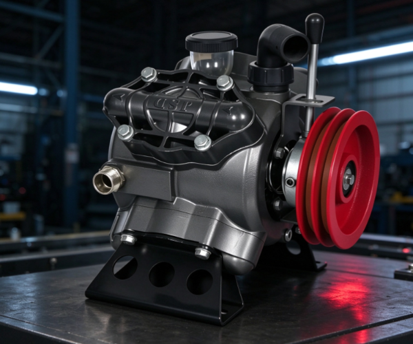
Operators, maintenance crews, and industrial buyers all benefit from knowing how these spare parts are built. You can name the components, see how they affect each other, and spot the ones that deserve a closer look during routine servicing.
Internal layouts differ from one design to another, but most pumps share the same basic building blocks. From the diaphragm and valve assembly to the housing and connection parts, every element has a defined place in the structure.
What Are the Main Components of a Diaphragm Pump?
A diaphragm pump is made of several linked components that move fluid together. The exact structure depends on the model and what it's used for. In general, though, you'll find the diaphragm, valve balls, valve seats, pump chambers, air distribution parts, and connecting hardware.
These parts fall into a few functional groups. Some handle the fluid directly. Others control how the pump operates or hold everything in place.
The table below lists common diaphragm pump spare parts and what each one does.
| Spare Part | Main Function |
|---|---|
| Diaphragm | Moves back and forth to change the volume of the pumping chamber |
| Valve Ball | Controls the direction of fluid movement |
| Valve Seat | Provides a contact surface for the valve ball |
| Pump Chamber | Holds the fluid during the pumping process |
| Manifold | Directs fluid into and out of the pump |
| Air Valve | Controls the movement of compressed air |
| Air Chamber | Provides space for air movement within the pump |
| Center Section | Connects and supports internal operating components |
| Seals and O-Rings | Help prevent fluid or air leakage |
| Bolts and Fasteners | Hold different pump components together |
No two pump designs are laid out in exactly the same way. Some add extra parts to handle particular fluids or harsh working conditions.
Take a chemical transfer pump. Its diaphragm and sealing materials will probably differ from those in a pump built for ordinary water. The internal structure may look much the same, but the materials and part design can change quite a bit.
Once you know the names and roles of these parts, it's much easier to see how a pump works and how each spare part affects its performance.
How Does the Diaphragm Form the Core of the Pump Structure?
The diaphragm is probably the part people recognize first. It's a flexible membrane that keeps the fluid chamber apart from the drive mechanism. Each time it moves, the space inside the pumping chamber changes, so liquid can flow in and then out.
Pumps with rotating impellers work differently. Here, the bending of the diaphragm creates the conditions for fluid transfer. It also acts as a barrier between two separate working areas of the pump.
Diaphragm designs vary with the model and the application. Some are made of flexible rubber. Others use materials chosen for chemical resistance or for compatibility with a specific liquid.
A typical diaphragm has a few key structural features:
- Flexible working area: This section bends during operation and changes the chamber volume.
- Outer edge: This part is clamped between neighboring pump components to hold the diaphragm in place.
- Central connection area: This is where the diaphragm attaches to the moving mechanism.
- Contact surface: The side facing the fluid has to suit the liquid being pumped.
Together, these features let the diaphragm flex again and again while keeping the fluid and the drive mechanism separate.
It also needs regular attention. Constant movement, exposure to different liquids, and shifting operating conditions wear it down over time. Cracks, warping, or surface damage can make the fluid transfer unstable.
When you replace a diaphragm, check its shape, material, connection structure, and fit with the pump. Two diaphragms can look the same from the outside and still not be interchangeable.
What Roles Do Valve Balls and Valve Seats Play?
The valve assembly is another key part of the pump. It decides which way the liquid travels. Without it, the pump would struggle to keep a consistent flow from inlet to outlet.
Valve balls and seats work as a pair. The ball shifts in response to pressure changes inside the pump, and the seat gives it a surface to close against.
During the suction stroke, pressure in the chamber changes. The inlet valve opens and liquid comes in. The outlet valve stays shut, so nothing flows backward.
Then the diaphragm moves the other way and pushes the liquid toward the outlet. The inlet valve closes and the outlet valve opens, letting the fluid leave.
Repeat that over and over, and you get a controlled transfer process.
| Component | Structural Role | Function During Operation |
|---|---|---|
| Inlet Valve Ball | Located in the inlet valve assembly | Allows liquid to enter the chamber |
| Outlet Valve Ball | Located in the outlet valve assembly | Allows liquid to leave the chamber |
| Valve Seat | Forms the contact surface for the ball | Helps control the opening and closing of the passage |
| Valve Housing | Holds the valve assembly in position | Supports the movement of the valve components |
Material choice affects where these parts can be used. Depending on the fluid and the environment, manufacturers may go with rubber, plastic, metal, or another compatible material.
Wear changes how well the valves open and close. A damaged ball may not seat properly. A worn seat can leave small gaps, and liquid will slip through in the wrong direction.
The results can include lower pumping efficiency, uneven discharge, or fluid flowing back to the inlet side.
For maintenance teams, the ball and seat relationship matters. If a pump delivers an irregular flow, inspect both parts together instead of treating them as two unrelated items.
How Are the Pump Chamber and Manifold Connected?
Together, the pump chamber and manifold make up the main fluid-handling structure. They supply the internal space and the flow passages that carry liquid through the equipment.
The chamber is where the diaphragm changes the volume. As the diaphragm moves outward, the space grows and liquid is drawn in. As it moves inward, the space shrinks and the liquid is pushed toward the discharge passage.
The chamber has to stay properly sealed throughout. Its inner surface must also be compatible with the fluid.
The manifold does something else. It ties the pump to external pipelines or hoses and guides the liquid coming in and going out. Depending on the design, the inlet and outlet passages can be arranged in different ways.
This section usually includes the following elements:
- Inlet passage: Gives liquid a way into the pump.
- Outlet passage: Guides the transferred liquid toward the discharge line.
- Connection ports: Link the pump to external pipes or hoses.
- Manifold body: Contains the internal flow passages and supports the connections.
- Sealing areas: Help stop leaks around joints and connection points.
These parts need to work as one. The fluid should follow a continuous, well-sealed path from start to finish.
A damaged manifold can leak or make pipeline connections awkward. Trouble inside the chamber can interfere with diaphragm movement or with the liquid flow.
Materials matter here too. If the pump handles corrosive liquids, the chamber and manifold must be made of something that can stand up to the fluid. Food or other sensitive products bring a different set of material requirements.
Before replacing these components, check where they connect and whether their structure matches the existing pump.
What Is the Function of the Air Distribution System?
Many industrial diaphragm pumps run on compressed air. In these designs, the air distribution system sends air to the correct side of the pump, and that is what moves the diaphragm.
Most of the attention goes to the fluid side, but the air side matters just as much. It governs how the pump's internal moving parts behave while running.
This system can include the air valve, air chambers, center section, and connecting passages.
The air valve steers the compressed air. It feeds air to different areas of the pump in a repeating sequence, which makes the diaphragm move back and forth.
The air chambers give the air room to move. They connect to the diaphragm assembly and help separate the air side from the fluid side.
The center section holds several internal components together and supports the operating mechanism.
Each part has its own structural role:
| Component | Structural Position | Main Purpose |
|---|---|---|
| Air Valve | Within the air distribution section | Directs compressed air |
| Air Chamber | Behind the diaphragm | Provides space for air movement |
| Center Section | Between the main pump sections | Connects and supports internal parts |
| Air Passages | Inside the pump structure | Guide air through the system |
| Air Seals | Around selected connections | Help prevent air leakage |
The air system has to stay in step with the diaphragm assembly. If the air valve is blocked or damaged, the diaphragm may not move the way it should. The pump might then run erratically or stop transferring fluid.
Air leaks cause trouble as well. Worn seals or loose connections make it hard to keep the air supply at the level the pump needs.
That's why air-side components belong in routine inspections. They shouldn't get skipped during maintenance.
Why Are Seals, O-Rings, and Fasteners Important?
Seals and fasteners look simple next to the diaphragm or the valve assembly. Even so, the pump's structure depends on them.
A pump is built from several connected sections, and they have to stay firmly joined while it runs. Fluid and compressed air must also stay inside their intended passages.
Seals and O-rings keep those paths separate. They normally sit between mating surfaces, around openings, or close to moving parts, and they cut down the chance of leaks.
Their shape and position depend on the pump design. Some are flat. Others are round or have a specially formed profile.
O-rings are common around connections and internal passages. Being flexible, they settle into their grooves and keep the joined surfaces in contact.
Fasteners do a different job. Bolts, nuts, and similar parts clamp the pump sections together and keep the diaphragm, chamber, manifold, and other structural elements where they belong.
The condition of these small parts can decide how reliable the whole assembly is.
A cracked O-ring, for example, can let fluid escape even when every major component is in good shape. A loose fastener can disturb the contact between surfaces and leave the seal uneven.
During maintenance, look for the following:
- Visible cracks, cuts, or deformation.
- Changes in flexibility or surface condition.
- Corrosion or physical damage.
- Loose or damaged threads.
- Incorrect positioning during installation.
- Signs of fluid or air leakage around connection points.
Swapping out worn seals and fasteners when needed helps keep the pump structurally sound. Use parts that match the original design, too, rather than choosing them just because they look right.
How Do Different Diaphragm Pump Spare Parts Work Together?
Every spare part has its own job, yet the pump only works because they all interact. A fault in one area can show up in another.
The diaphragm produces the movement that transfers the fluid. The valve assembly sets the direction of flow. The chamber and manifold provide the fluid passages, and in air-operated designs the air distribution system drives the diaphragm.
Seals and fasteners keep all of those sections assembled properly.
The relationships are easier to follow if you look at the pumping process as one full cycle.
| Operating Stage | Main Component Movement | Related Spare Parts | Pump Response |
|---|---|---|---|
| Suction | Diaphragm moves to increase chamber volume | Diaphragm, inlet valve ball, valve seat | Liquid enters the chamber |
| Discharge | Diaphragm moves to reduce chamber volume | Diaphragm, outlet valve ball, valve seat | Liquid moves toward the outlet |
| Air Distribution | Air supply changes direction | Air valve, air chamber, center section | Diaphragm movement continues |
| Sealing | Connected surfaces remain closed | O-rings, seals, fasteners | Fluid and air remain within their intended passages |
This is also why changing a single component doesn't always fix the problem.
Uneven discharge, for instance, could point to a worn diaphragm. It could just as easily come from damaged valve balls or seats. Likewise, an air leak may start at a seal and not in the air valve at all.
A sensible maintenance routine looks at the related components together.
When one part shows wear, check its neighbors too. That tells you whether the fault sits in one spare part or reflects a wider assembly problem.
What Should You Consider When Selecting Diaphragm Pump Spare Parts?
Choosing the right spare parts means understanding both the pump's structure and the conditions it works in. Two components can look alike and still differ in size, material, connection design, or installation position, and any of those can cause a compatibility problem.
Start with the pump's current configuration. Identify the model and check the relevant parts information, and you'll find it easier to locate components that match the original assembly.
Material compatibility comes next. Fluids react with pump materials in different ways. Some liquids make certain rubbers swell or go stiff, and others attack metal or plastic surfaces.
The working environment plays a part as well. Temperature swings, frequent operation, and abrasive media can all speed up wear on certain components.
A few factors deserve attention when picking replacements.
1. Structural compatibility
The replacement should match the original in shape, connection position, and installation requirements. This matters most for diaphragms, valve assemblies, and sealing components.
2. Material suitability
The material should work with the transferred liquid and the surrounding conditions. That lowers the risk of early wear or material damage.
3. Component condition
Inspect spare parts for visible defects before fitting them. Cracks, deformation, damaged surfaces, and uneven dimensions can all rule a part out.
4. Assembly requirements
Some components belong to a complete assembly. If you replace a valve ball without checking its seat, an existing problem may stay unsolved.
5. Maintenance needs
Parts that are inspected or replaced often should be easy to identify and reach. Clear spare part information lets maintenance teams prepare the right replacements and plan servicing.
A good grasp of diaphragm pump spare parts also helps buyers talk to suppliers. Rather than asking for a generic replacement, they can state the part they need, where it sits, its material, and the pump configuration.
That keeps the selection process simple and cuts the chance of receiving an incompatible component.
 Previous
